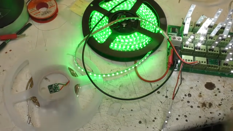
While addressable LED strips are all the rage, [Mike] from [mikeselectricstuff] has been working on an installation using the more basic two-wire strips that are simply controlled via PWM dimming. He’s recently figured out a tidy way to send sensor signals down these strips without adding any additional cabling.
The build uses 24 V LED tape, which consists of gangs of 6 LEDs in series with a forward voltage of 3V. Thus, these strips don’t even begin to light until approximately 18V is across them.
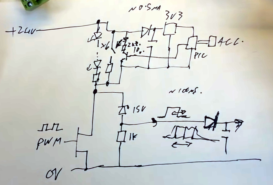
By adding a 15 V Zener diode and a resistor across the MOSFET which dims the LEDs, a voltage of around 9 V can be put across the LEDs without lighting them up when the MOSFET PWM dimmer is in its off phase. A PIC10F322 microcontroller and an accelerometer can then be run from this voltage, with the aid of a 3.3 V regulator wired in parallel with the LEDs. The regulator must also be able to handle the full 24 V when the LEDs are switched on.
A transistor is also wired up, switching a 2.2 K resistor in parallel with the LEDs. When turned on by the PIC, this transistor causes roughly a 10 mA current to flow through the Zener diode and its series resistor. The voltage developed across that series resistor can be measured as the transistor is turned on and off. In this case, the pulse width used to turn that transistor on is relative to motion detected by the accelerometer on the end of the LED strip.
Turning the LEDs on at 100% duty cycle prevents the system working, as the pulse widths generated by the sensor circuit can’t be detected when the LED line is held high all the time. However, in practice, it matters not — running the LEDs at a maximum 98% duty cycle eliminates the issue.
It’s an ingenious way to send sensor signals down a two-wire LED strip, even if it does take a second to wrap one’s head around it. It also seems to do a great job of adding motion-reactive effects to the LED strips in question. It’s not the first LED project we’ve seen from [Mike], either. Video after the break.
[Thanks to Tim Gremalm for the tip!]


Very clever!
Not a lot unlike addressable fire alarm equipment which I used to be involved with. To be able to communicate with one or more devices (smoke detector, callpoints, sounders) on a pair of wires the fire alarm panel would send a series of voltage pulses superimposed on top of a nominal 24vdc supply. The responding device would then communicate by sinking or not sinking current to send a digital reply, similar to OOK.
Any example circuits allowing this kind of 2 wires date over DC power supply?
Use a standard h-bridge motor controller like the DRV8838. Pull the enable pin high to supply DC to the receivers on the line or low to stop supplying voltage. Modulate your signal by controlling the phase pin, switching which wire has the supply + and which the supply -.
At the receiving end, connect the two wires to the AC pins of a bridge rectifier to recover the DC supply voltage. Feed the two wires to the inputs of an op-amp and get your data signal at the output. Since this is a balanced circuit, if you use twisted-pair wiring the op-amp will also cancel out the majority of induced noise on the line.
Thanks, but if i understand your description well, this is not superimposing voltage pulses on top of a nominal DC supply, like for the equipements described by ColinM, but rather modulating DC power supply, which is rather different. Being able to modulate a signal over a constant power supply seems more interesting for me.
Common adjustable buck and boost regulators have a feedback pin that allows the output voltage to be adjusted. Usually this means setting up a voltage divider across the output that results in the feedback pin getting a specific target voltage when the output voltage equals the output you want. Adjustable power supplies use a pot with the opposite ends across the output and the wiper connected to the feedback pin. You could use a digital pot to vary the output voltage under the control of a microcontroller, but I’m not sure how fast you can vary the voltage.
Reminds me of the LED rope lights sold by Costco the past three years. LEDs in series across rectified DC from the mains, with only two wires. BUT – there are a variety of colors and patterns one can invoke – but no control signal.
It turns out that the control box sends brief pulses of no-current during part of the (rectified) AC Cycle, which each LED interprets. Each LED in each series string receives the signal and goes into the desired mode (color and optional pattern).
Alas, the same signal goes to all (enhanced chip) LEDs – they cannot be controlled individually, which is what I wanted. In the multi-color mode, each LED makes it’s own random choice of color.
Reminder to self – be VERY careful using a mains powered O’scope on a mains-derived high voltage line when looking for transient signals (Isolation transformer and careful probing). The scope survived luckily, but one rope lighht control box did not.